Table of Contents
1. Mathematical Models, Estimation and Attitude Control Algorithms
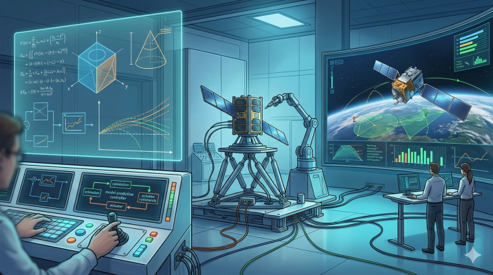
To orient the satellite in the desired direction, data from sensors is processed through the satellite’s mathematical models and sent to the actuators as commands. This process relies on three fundamental building blocks:
1. Satellite Kinematics Kinematics describes only the geometry of the satellite’s motion without accounting for forces and mass. It is used to mathematically express where the satellite is instantaneously pointing (its attitude) in space. It is generally calculated using Euler Angles (Roll, Pitch, Yaw), which are easy to understand, or Quaternions, which are mathematically more robust.
2. Satellite Dynamics Dynamics examines the satellite’s mass, inertia, and the forces and torques acting upon it. Disturbances in space (Solar radiation pressure, magnetic field, gravity gradients, etc.) and the rotational forces generated by actuators are the subjects of dynamics. How a satellite physically responds to an applied torque is modeled by Newton and Euler laws.
3. Fundamental Controllers After modeling the kinematic and dynamic systems, controllers step in to eliminate the error between the target and the current state. The most basic and common method is PID (Proportional-Integral-Derivative) control. By continuously calculating the margin of error, the controller determines exactly how much power must be supplied to the actuators for the satellite to remain stable in the desired orientation.
Ongoing Research and Future Control Systems Although basic controllers are sufficient for standard missions, space missions are becoming increasingly difficult. The current objective is to develop systems that consume much less energy/fuel, can maneuver much faster, and prevent system failure against the unknown disturbances of outer space and potential hardware malfunctions within the satellite (robust and adaptive systems).
To achieve these goals, many control studies are still ongoing using methods such as Artificial Intelligence, Fuzzy Logic, and Adaptive Control.
2. Terrestrial Verification Tests and Simulation Infrastructures
Verifying a spacecraft’s ADCS software and hardware on Earth before launch is crucial to guarantee mission success. In space, except for exceptional cases (like Hubble maintenance missions), hardware replacement or physical repair is very difficult. In this context, Hardware-in-the-Loop (HITL) tests have been developed to test the satellite’s computers, sensors, and actuators by simulating the space environment [A review paper: The dynamics, kinematics, design and control of satellite simulators with spherical air bearing].
2.1. Spherical Air Bearings
Spherical Air Bearing systems are the most sophisticated engineering solution for recreating the frictionless and micro-gravity conditions of the space environment on Earth. Platforms floating on a hemispherical bearing, where high-pressure air creates a thin film layer, allow the satellites placed on them to rotate with almost zero friction. Spherical air bearings enable full attitude control tests with 3 Degrees of Freedom (3-DOF): 360 degrees (unconstrained) in the Z-axis, and +-15 degrees in the X and Y axes.
The critical phase of these tests is aligning the platform’s Center of Mass with its center of rotation at a very precise level. Under Earth’s massive gravity, the slightest offset of these two centers creates a very strong parasitic gravitational torque that does not exist in space, rendering the test invalid. Linear sliding mass balancing systems are used to achieve this alignment.
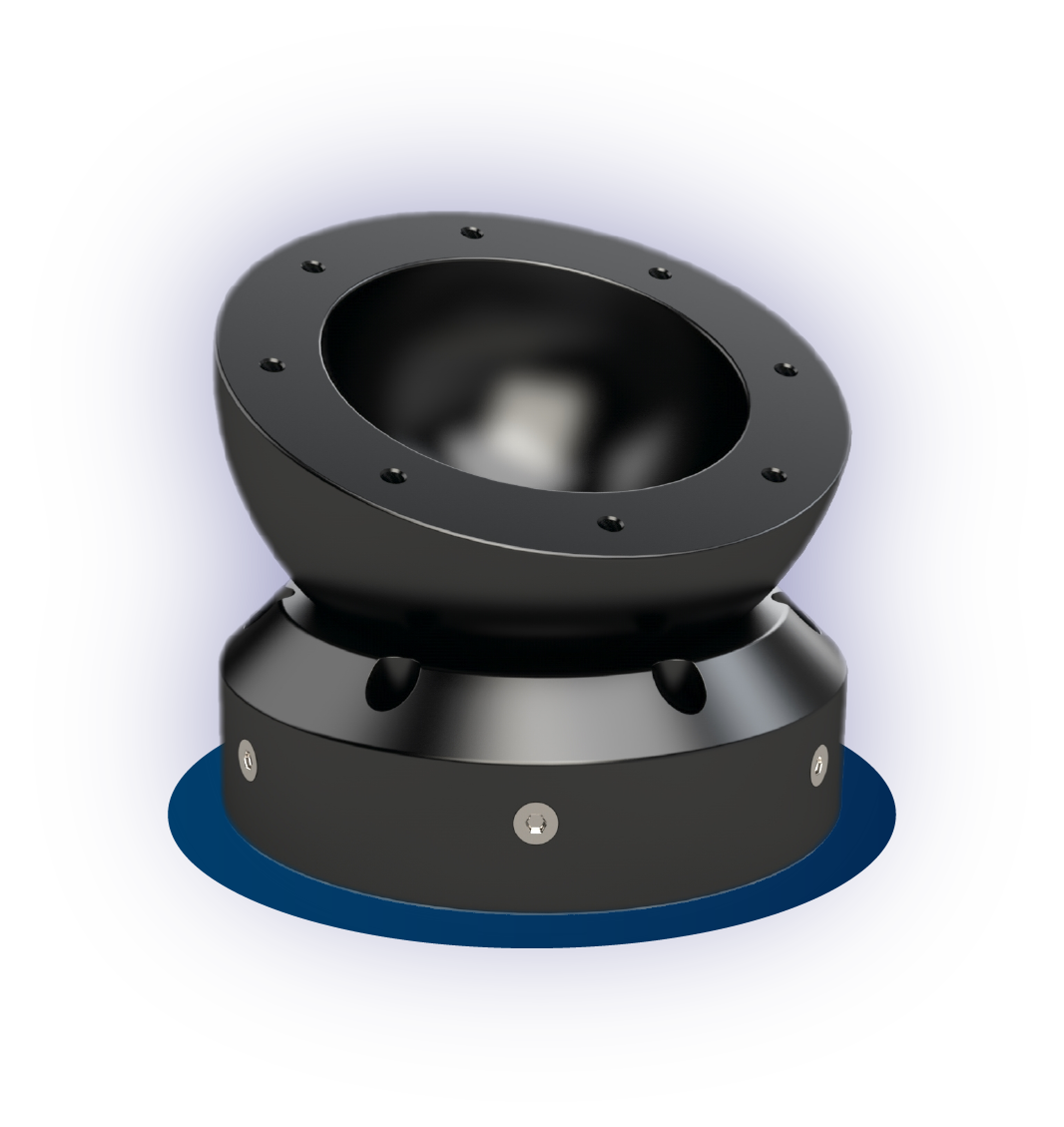
Bring Space Conditions to Your Laboratory
Turn the terrestrial verification concepts you are reading about into a physical test. Our high-precision SPACROL Spherical Air Bearing systems allow you to verify your satellites’ attitude control algorithms in a frictionless environment.
Spherical Air Bearing systems are the most sophisticated engineering solution for recreating the frictionless and micro-gravity conditions of the space environment on Earth. Platforms floating on a hemispherical bearing, where high-pressure air creates a thin film layer, allow the satellites placed on them to rotate with almost zero friction. Spherical air bearings enable full attitude control tests with 3 Degrees of Freedom (3-DOF): 360 degrees (unconstrained) in the Z-axis, and +-15 degrees in the X and Y axes. The critical phase of these tests is aligning the platform’s Center of Mass with its center of rotation at a very precise level. Under Earth’s massive gravity, the slightest offset of these two centers creates a very strong parasitic gravitational torque that does not exist in space, rendering the test invalid. Linear sliding mass balancing systems are used to achieve this alignment.
In this context, the SACSTOR product developed by SPACROL is an advanced technology satellite attitude control simulator with Hardware-in-the-Loop (HIL) capability that bridges the gap between software simulations and orbital reality. Realized with the support of TÜBİTAK, this innovative system floats the payload on a microscopic layer of pressurized air, almost completely eliminating mechanical friction and allowing even the smallest torques to be measured. Thanks to the high-precision mass balancing mechanisms integrated into the device, the satellite’s center of gravity is perfectly aligned, reducing gravity-induced parasitic torques to almost zero. With a 1600 N spherical air bearing capacity and operating with a pointing accuracy of less than 1 degree, SACSTOR provides a flawless environment for minimizing mission risks by testing especially 3U and 6U CubeSat architectures before launch.
The most critical engineering advantage that distinguishes the system from standard test infrastructures is its customizable actuator architecture. SACSTOR performs active 3-axis attitude control with its own 4 pyramidal reaction wheels. If desired, this structure can also be produced with a custom design change upon order. With its dual IMU sensors, high-capacity battery infrastructure (121 Wh), and wireless communication equipment, it ensures that developed algorithms are safely tested on Earth. SACSTOR is an indispensable verification and calibration platform for engineers in closed-loop tests of control algorithms developed against external disturbance torques and hardware failures.
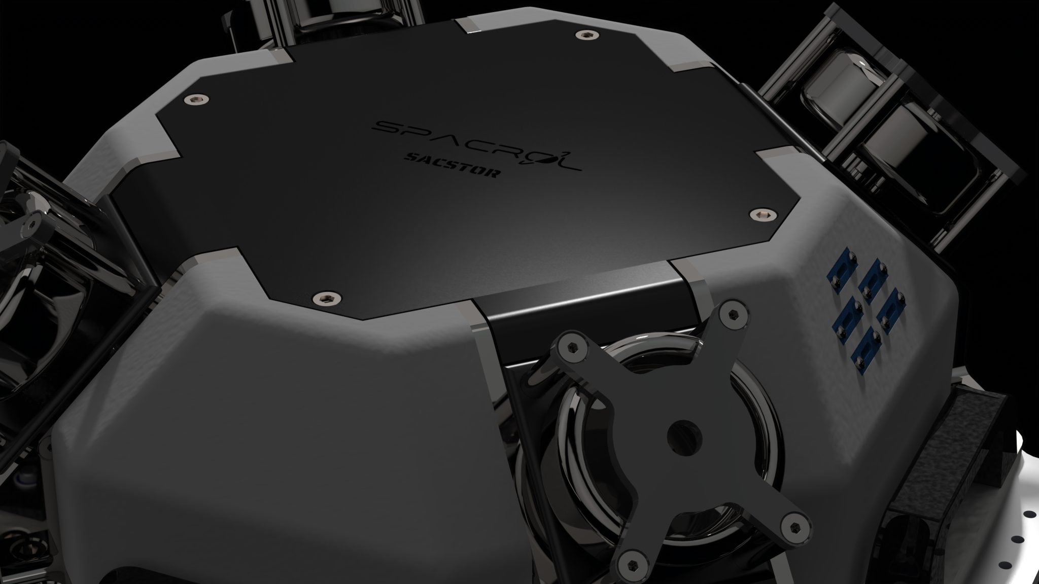
Complete Hardware-in-the-Loop (HIL) Satellite Simulation
Experience the dynamic behaviors of your satellites in space as close to reality as possible on Earth. The SPACROL SACSTOR Satellite Attitude Simulator provides a strategic terrestrial verification infrastructure that allows you to test your attitude determination and control (ADCS) subsystems, actuators, and algorithms in an integrated laboratory environment.
On the other hand, not every test platform has to be 3-axis. Another product of SPACROL, 1D4T: Single Axis Attitude Control Test System, was developed as a cost-effective 1 Degree of Freedom (1-DOF) experimental device that allows rotation only in the Z-axis, in order to simplify complex mass balancing problems and focus solely on Yaw rotation algorithms. Emerging with the “1 System, 4 Tests” vision, this platform brings together not only standard attitude determination (ADCS) scenarios but also high-resolution DC motor control, dynamic inertia analyses based on the Parallel Axis Theorem, and reaction wheel tilt tests in a single compact body.
One of the most striking innovations of 1D4T is its reconfigurable actuator architecture. The system provides attitude control with reaction wheels. However, these wheels do not have to remain on a fixed axis; if desired, the angle of the reaction wheel can be changed mechanically, transforming into advanced pyramid structures and different orthogonal configurations encountered in real space missions. Thanks to this unique flexibility, engineers have the opportunity to verify multiple ADCS strategies on the same platform without the need for different hardware setups.
Offering a complete solution for Hardware-in-the-Loop (HIL) test infrastructure, 1D4T provides real-time data flow with its custom-designed high-resolution 16-bit PWM controlled driver layer, precise IMU sensors, USB Type-C, and wireless communication options. The system, which has direct integration with many software platforms, simplifies the processes of developing and testing modern control algorithms thanks to its Graphical User Interface (GUI) compatible with PCs and mobile devices.
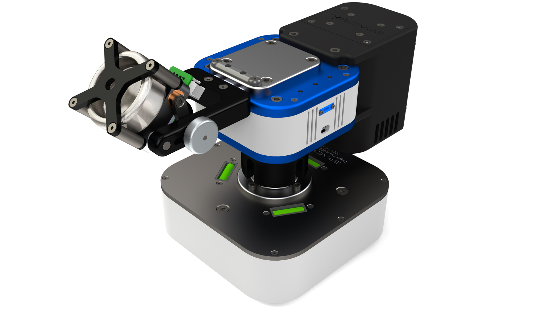
Test Your Algorithms with Real Hardware
Do not leave the attitude control algorithms you developed in computer simulations. With the SPACROL 1D4T Single Axis Attitude Control Test Setup, verify your mathematical models on physical hardware (HIL) with high precision and analyze the system dynamics in real-time.
2.2. Magnetic Simulators: Helmholtz Cages and NASA Facilities
For the verification of magnetic torquers and magnetometers, the magnetic field of the Earth and the orbit where the satellite will be located (e.g., LEO) must be synthesized accurately in the terrestrial laboratory. This process is generally performed with giant “Helmholtz Cages” surrounding the air bearing [76]. These systems, consisting of giant coil pairs positioned orthogonally on three axes, operate with computer-controlled currents. For sensor tests, they first completely cancel (nullify) the existing Earth magnetic field of the room they are in, and then dynamically simulate the magnetic flux lines changing from second to second in LEO over the orbital model of the satellite. Custom-developable Helmholtz Cages can be provided by SPACROL upon request.
The historical and globally most prestigious structure of magnetic test engineering is the Spacecraft Magnetic Test Facility at NASA Goddard Space Flight Center, located in Maryland. Built in 1966, this legendary building gained National Historic Landmark status in 1985. The facility’s building was constructed entirely of non-magnetic materials (using wood and aluminum nails) to prevent magnetic interference that could originate from the outside or the building itself, and it is isolated in a wooded area away from the power lines leading to the center.
Inside the building, there is a 3-axis Braunbek Coil System consisting of 4 giant spirals, which is superior to a standard Helmholtz cage. This massive coil system, approximately 13 meters (42-foot) in diameter, nullifies the Earth’s magnetic field and creates a 1.8-meter highly stable (half nanotesla stability) “magnetically completely quiet” spherical working volume at its center. Since the early years of the space race, the magnetometer calibration of hundreds of spacecraft, from the Lunar Rovers of the Apollo program to giant communication satellites, and from modern Mars missions to today’s nanosatellites, has been carried out thanks to these unique Braunbek coils. The facility is also responsible for limiting magnetic interference by measuring how much magnetic interference (magnetic dipole moment) the satellite emits into space from its own electronic circuits while completely powered on [84-88].
3. General Evaluation and Future Perspectives
Attitude Determination and Control Systems (ADCS) have followed a unique evolutionary process from the one-dimensional tumble damping efforts of Explorer 1 to the arc-second precision vision of the Hubble Telescope; from the mechanical gyroscopes of the Apollo era to modern CubeSat modules the size of smartphone processors. Adapted to the characteristic structure of the orbit (atmospheric drag in LEO, solar radiation pressure in GEO), these systems are the backbone of spacecraft platforms’ ability to autonomously survive and execute missions in space.
Traditional PD, PID, and LQR-based approaches have been the main pillar in the attitude control of spacecraft for many years. However, the unpredictable nature of space, external disturbance torques, actuator constraints, and non-linear satellite dynamics make ADCS one of the most challenging and still rapidly developing research areas of engineering. To overcome these complex problems, the integration of artificial intelligence-supported hybrid architectures into flight computers is shaping the future of ADCS theory. With advancing technology, it is clear that satellites operating in space missions will continue to be equipped with artificial intelligence-supported autonomous ADCS architectures capable of overcoming all kinds of environmental disturbance torques.
The fact that theoretical algorithms are tested and combined with hardware in NASA’s historic Braunbek coils, Helmholtz cages, and spherical air bearings before reaching space shows that failure is unacceptable in the space industry. Seeing how mathematically flawless-looking next-generation artificial intelligence algorithms will cope with real-world hardware delays and physical anomalies is only possible with high-precision physical simulations. Exactly at this point, top-tier Hardware-in-the-Loop (HIL) test platforms like SACSTOR are needed to bridge the gap between software and orbital reality.
SACSTOR can safely verify even the most complex control architectures developed by creating the frictionless dynamics of the space environment on Earth with minimal flaws. In short, while SACSTOR minimizes the risk of failure in orbit at the hardware level in modern space operations, it paves the way for the much faster and lower-cost development of the AI-supported independent satellite technologies of the future, and provides significant opportunities for students in engineering education.