Table of Contents
1. Historical Evolution of Attitude Control
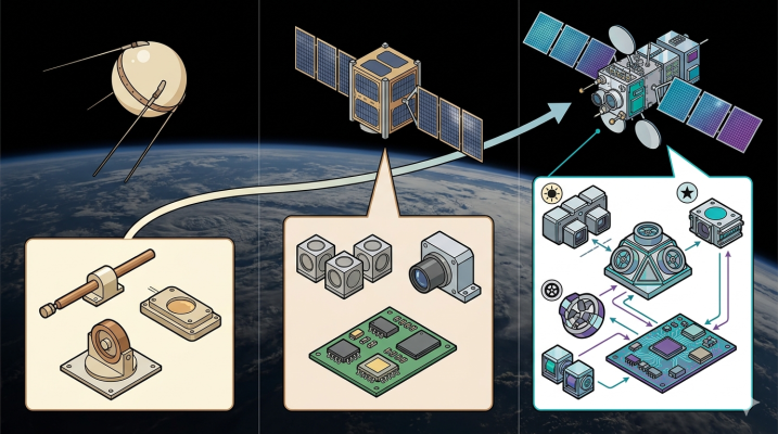
Attitude determination and control technologies have undergone an extraordinary engineering evolution from the dawn of the space age to today’s constellation concepts. In the early days of space exploration, minimizing system complexity and potential failure points was the primary priority. Pioneering vehicles like Sputnik 1, launched by the Soviet Union in 1957, and the USA’s first satellite Explorer 1, which followed in 1958, lacked an active attitude control mechanism and tumbled freely in space [17].
The first systematic approach adopted to overcome the operational constraints caused by this lack of control was “spin stabilization” [8]. Spin stabilization is based on the principle of rotating the cylindrical or symmetrical body of the spacecraft around its own axis at a speed of 50 to 100 revolutions per minute (rpm), much like a top [23]. The angular momentum created by the rotational movement provides gyroscopic stiffness due to Newtonian mechanics, ensuring the axis of rotation remains fixed in space. Successfully applied in historic missions such as Pioneer 10 and 11, Lunar Prospector, and the Galileo Jupiter orbiter, this method was considered the standard for many years as it offered high stability with a minimum of moving parts [8]. However, spin stabilization had a fundamental weakness: since the body of the vehicle was constantly rotating, solar panels and cameras mounted on the exterior could only see their targets during a small fraction of the rotation period, scanning them almost like a lighthouse [24].
The first major steps towards controlling the attitude axis of early satellites from Earth were taken in the 1960s. The TIROS II meteorological satellite, launched in 1960, featured a pioneering system that used magnetic torque generators to orient the spin axis. The direction of the electrical current passed through a conductive coil wrapped around the satellite’s outer shell was altered by commands sent from the ground station based on data received from Sun and horizon sensors; as a result of the interaction of this artificial magnetic field with the Earth’s magnetic field, the satellite’s spin axis was directed to the desired position via precession motion. This innovative concept, patented by Hughes Aircraft Company, revolutionized attitude control [26]. The paradigm shift that formed the basis of modern space operations was the transition to the “3-axis stabilization” concept, where the body is kept completely fixed in space. The historical turning point in this field was the Applications Technology Satellite 6 (ATS-6) mission launched by NASA in 1974. ATS-6 went down in history as the first spacecraft to feature 3-axis stabilization in Geostationary Earth Orbit (GEO) [28]. With its 930-kilogram mass and 9-meter parabolic antenna, ATS-6 abandoned spin motion and was able to lock its antenna onto rural areas of the USA and the SITE (Satellite Instructional Television Experiment) project in India with unprecedented precision; thus proving the feasibility of direct broadcast and tele-education concepts [29]. This success of ATS-6 also led to a radical design change in meteorological satellites; the spin-stabilized GOES A-C satellites (which could only image 10% of the Earth) were replaced by the new generation GOES satellites, starting with GOES-8 launched in 1994, which were 3-axis stabilized and capable of continuous, simultaneous imaging and sounding of 100% of the Earth [24].
National Environmental Satellite, Data, and Information Service [24]
Entering the 21st century, breakthroughs in micro-electro-mechanical systems (MEMS) and the space-qualification adaptation of commercial off-the-shelf (COTS) electronic components initiated the “SmallSat” and “CubeSat” revolution [33]. In this process, pioneered by the NASA Ames Research Center and maturing with The Aerospace Corporation’s AeroCube series, complex ADCS hardware such as star trackers and reaction wheels—formerly exclusive to satellites weighing hundreds of kilograms—could be packed into small volumes like 1U (10x10x10 cm). AeroCube-4, launched in 2012, proved as the first CubeSat capable of 3-axis attitude control in a 1U form factor that small satellites were not just academic toys, but could also conduct commercial and military precision observation missions [35]. Today, NASA’s “Small Spacecraft Technology State-of-the-Art” reports document the current level of ADCS hardware, detailing how interplanetary CubeSat missions like Mars Cube One (MarCO) accomplished deep space communication relay tasks thanks to their autonomous attitude control systems [34].
2. Hardware Architecture of the Attitude Determination and Control System
The spacecraft attitude determination and control system (ADCS) consists of sensors acting as the satellite’s “sensory organs” and actuators acting as its “muscles.” These components are combined with control algorithms running on onboard computers to ensure the satellite maintains its targeted orientation throughout the mission.
2.1. Attitude Determination Sensors
Attitude determination is the process of defining the satellite’s current orientation relative to absolute or relative reference frames. For system reliability, data from multiple sensors are usually combined using filters (such as the Kalman Filter) in a process known as sensor fusion [1,3].
1. Star Trackers: They are the most precise absolute attitude sensors of modern ADCS architecture. By using an optical camera system, they take a high-resolution digital photograph of the sky. The flight software algorithmically matches the star patterns and their magnitudes in the image with the star catalog in the satellite’s memory. This process can provide the satellite’s 3-axis attitude in the inertial reference frame with an error margin of a few arc-seconds.
2. Sun Sensors: They determine the spacecraft’s attitude relative to the Sun vector. “Coarse Sun Sensors” (CSS) basically consist of photodiodes that measure light intensity and are used to direct the solar panels toward the energy source during the satellite’s Safe Mode conditions. “Fine Sun Sensors” (FSS), on the other hand, are more advanced optical detectors offering sub-degree accuracies within a narrow field of view.
3. Magnetometers: They measure the direction and intensity of the local magnetic field where the satellite is located. Typically, fluxgate magnetometers are used. This measured vector is compared with Earth magnetic field models, such as IGRF or WMM (World Magnetic Model), in the satellite’s computer to provide a rough or mid-level attitude estimation. They are effective only for LEO satellites and can be affected by the electromagnetic noise emitted from the satellite’s own electronic hardware.
4. Gyroscopes & IMUs: Rather than pointing to an absolute direction, they are relative sensors that measure the “angular rate” of the satellite. They enable the continuous integration and estimation of attitude data during intervals when horizon or star sensors cannot provide data (for example, when the satellite enters the Earth’s eclipse). Traditional mechanical gyroscopes have been replaced by Fiber Optic Gyroscopes (FOG) and MEMS gyroscopes due to weight and power advantages. The bias drift errors of gyroscopes that accumulate over time can be corrected with periodic absolute measurements taken from star trackers.
5. Earth Horizon Sensors: They detect the intersection of the planet with the cold vacuum of space (the horizon line) by sensing the infrared radiation emitted by the Earth (usually in the carbon dioxide band). This data is used to calculate the nadir (towards the center of the Earth) vector.
2.2. Attitude Control Actuators
Attitude control is the physical rotation of the satellite to nullify the attitude error. This rotation process is carried out by actuators based on Newton’s third law (action-reaction) and the principles of conservation of angular momentum [2].
1. Reaction Wheels (RW): They form the backbone of active 3-axis control. Integrated into the satellite body, these wheels are accelerated or decelerated via an electric motor. When the angular speed of the wheel changes (accelerates), due to the law of conservation of angular momentum, the satellite body begins to rotate in the opposite direction. Satellites typically have four reaction wheels, one of which is a redundant spare.
2. Magnetic Torquers / Torque Rods: They are conductive wire coils with magnetic cores. When current is passed through the coils, the spacecraft turns into an artificial electromagnet. This magnetic field interacts with the Earth’s natural magnetic field, creating a physical torque () on the body of the satellite [3]. Although they are too slow for main maneuvers, they are critical for “momentum dumping” (or desaturation) to discharge the momentum that accumulates in the reaction wheels over time due to aerodynamic and solar radiation torques, reaching the “saturation” point by exceeding the motor speed limit. This transfers the momentum to the Earth’s magnetic field without consuming system propellant.
3. Control Moment Gyros (CMG): They are systems that produce massive gyroscopic torques by pivoting massive, constant, high-speed spinning rotors around an axis (gimbal). They are used on the International Space Station (ISS) or highly agile observation satellites that require very fast slew maneuvers.
4. Thrusters: They create a reaction force by expelling pressurized cold gas, chemical propellants like hydrazine, or ionized plasma from nozzles placed around the spacecraft. They can produce very high and sudden torque, but since they are limited by propellant mass, they are reserved for trajectory correction and orbit maintenance operations. Furthermore, they are an important method for reaction wheel momentum dumping in regions where the magnetic field is weak, such as GEO.